· 9 min read
How to Perform a 4-20 mA Loop Check (and Why It Isn't a Calibration)
A practical, step-by-step guide to loop checking a 4-20 mA signal during commissioning — how to inject the signal, why three points are enough, and how to troubleshoot the failures that show up every time.
By MGTrace
loop checkcommissioning4-20 mAqualificationGMPpharma
Before a pharmaceutical line produces a single batch, someone has to prove that every signal is wired and scaled correctly. That job is the loop check, and for analogue signals it's where most installation errors surface.
It's also one of the most commonly misunderstood activities in commissioning, because loop checks and calibration get mixed up — and they are not the same thing.
A Loop Check Is Not a Calibration
This distinction matters, so let's settle it first.
Calibration is about the accuracy of the instrument. You compare the instrument's reading against a certified reference standard, you determine its error, and you adjust it if needed. It produces a calibration certificate, it has traceability to national standards, and it belongs to the instrument.
A loop check is about the path. You are verifying that a signal leaving the field arrives at the PLC, gets scaled correctly, and is displayed correctly on the HMI — and, for outputs, that a command leaves the PLC and reaches the device. It belongs to the installation, not to the instrument.
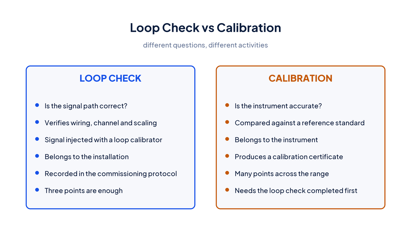
They answer different questions. Calibration asks "does this transmitter measure correctly?" A loop check asks "is this signal wired, mapped and scaled correctly from end to end?"
Part of the confusion comes from the tool itself: a calibrated 4-20 mA generator is commonly used to perform the loop check. Using a calibrated instrument to inject a signal is not the same as calibrating the measurement.
That difference is exactly why you don't need many test points.
What the Loop Check Covers
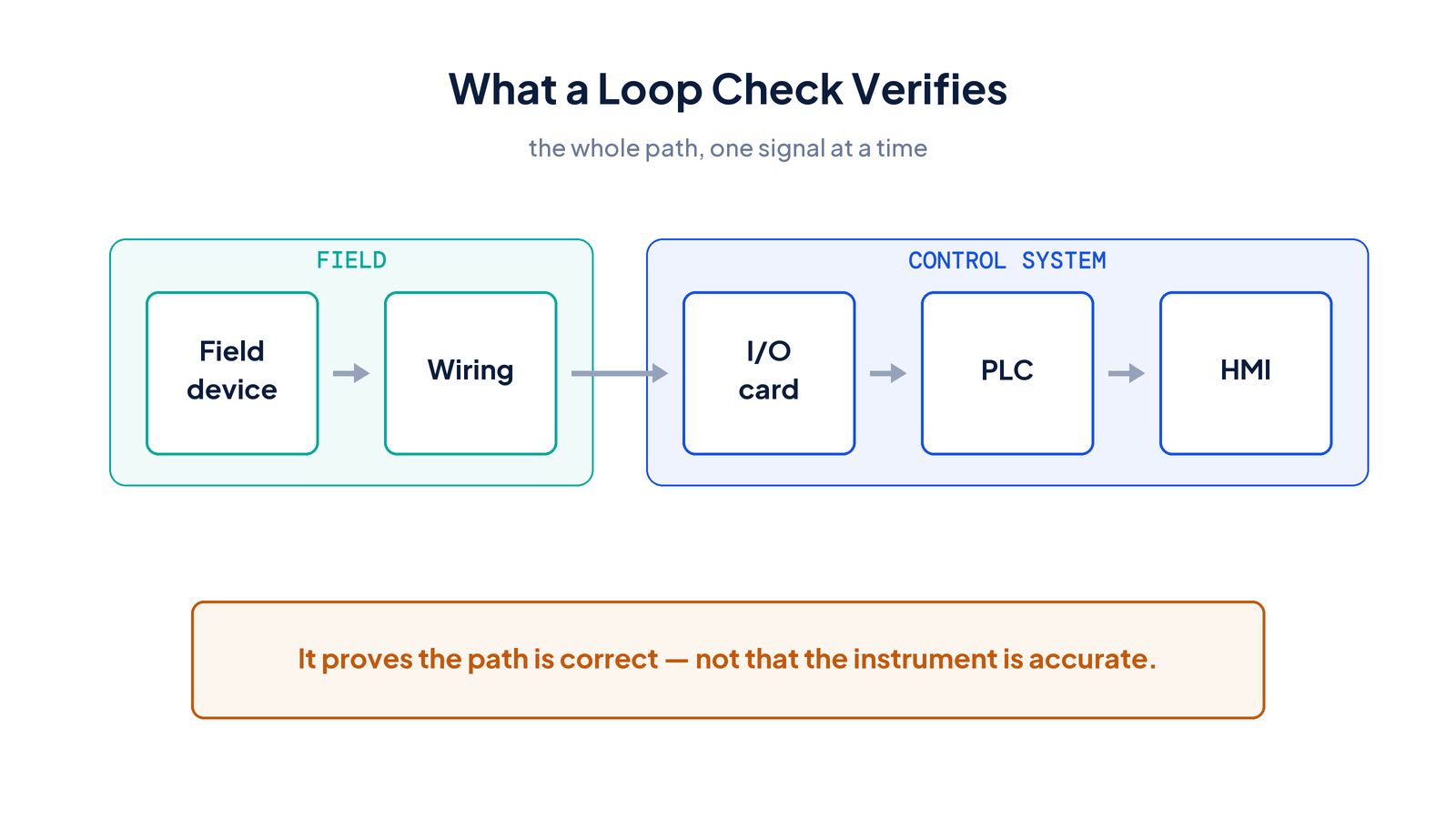
The full 4-20 mA signal path: field device, wiring, I/O card, PLC, and HMI. Every link in that chain, one signal at a time.
Why Three Points Are Enough
For a loop check, 0%, 50% and 100% of the range is sufficient — typically 4 mA, 12 mA and 20 mA.
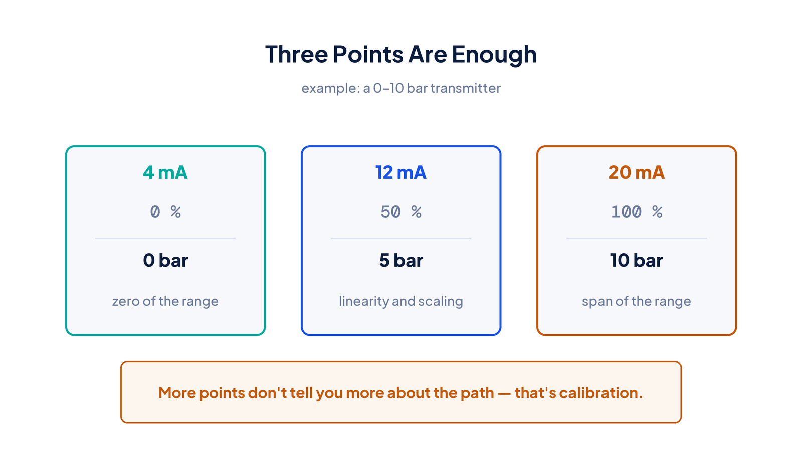
Those three points detect everything a loop check is meant to detect:
- 4 mA confirms the zero of the range and shows up any offset.
- 12 mA confirms linearity and, above all, catches reversed or incorrectly configured scaling — a loop that is perfect at zero can be completely wrong at midpoint.
- 20 mA confirms the span and catches a wrong range.
Adding more points doesn't tell you anything new about the signal path. If you are looking for accuracy across the measuring range, you are no longer doing a loop check — you are doing a calibration, and that's a different activity with different documentation.
The order also matters in practice: verify the loop first, then calibrate the installed instrument. Calibrating a loop whose wiring, channel or scaling has not been verified means you may be calibrating against the wrong signal path altogether.
How to Perform the Loop Check
Four steps, in this order.
Step 1 — Check the wiring and polarity
Before injecting anything, verify the wiring against the design: the correct terminals, the correct card, the correct channel.
Pay particular attention to polarity. In a current loop, reversed polarity is one of the most common installation errors and it doesn't always fail obviously — sometimes you get no signal, sometimes a saturated reading, sometimes something that looks almost plausible.
Step 2 — Inject the signal
There are two ways to inject a 4-20 mA signal, and both are valid.
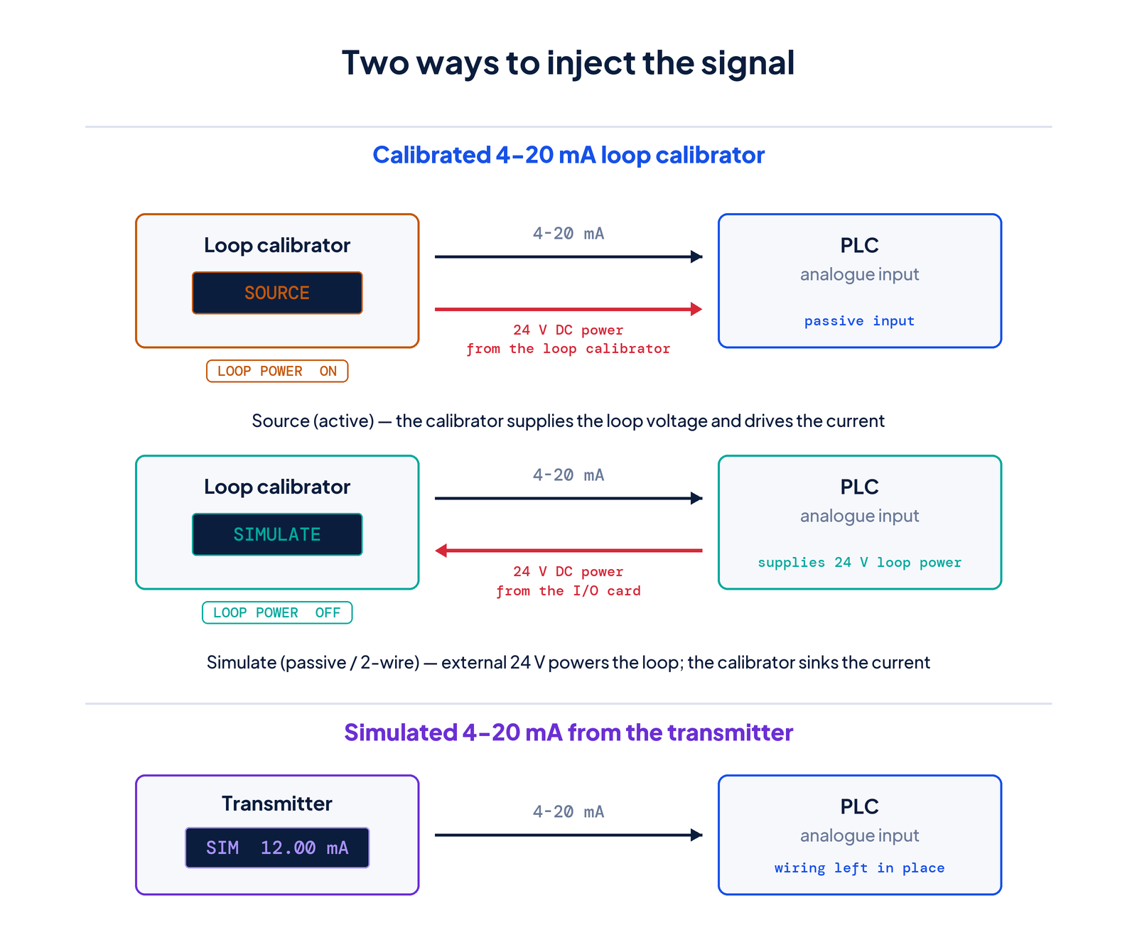
Option 1 — Use a calibrated 4-20 mA loop calibrator. Disconnect the transmitter wiring and inject the current with a loop calibrator. The calibrator has two modes, and choosing the right one depends on where the loop power comes from:
- Source (active) — the calibrator supplies the loop voltage and drives the current. Use it against a passive input, meaning a PLC analogue input card that does not provide its own 24 V field supply.
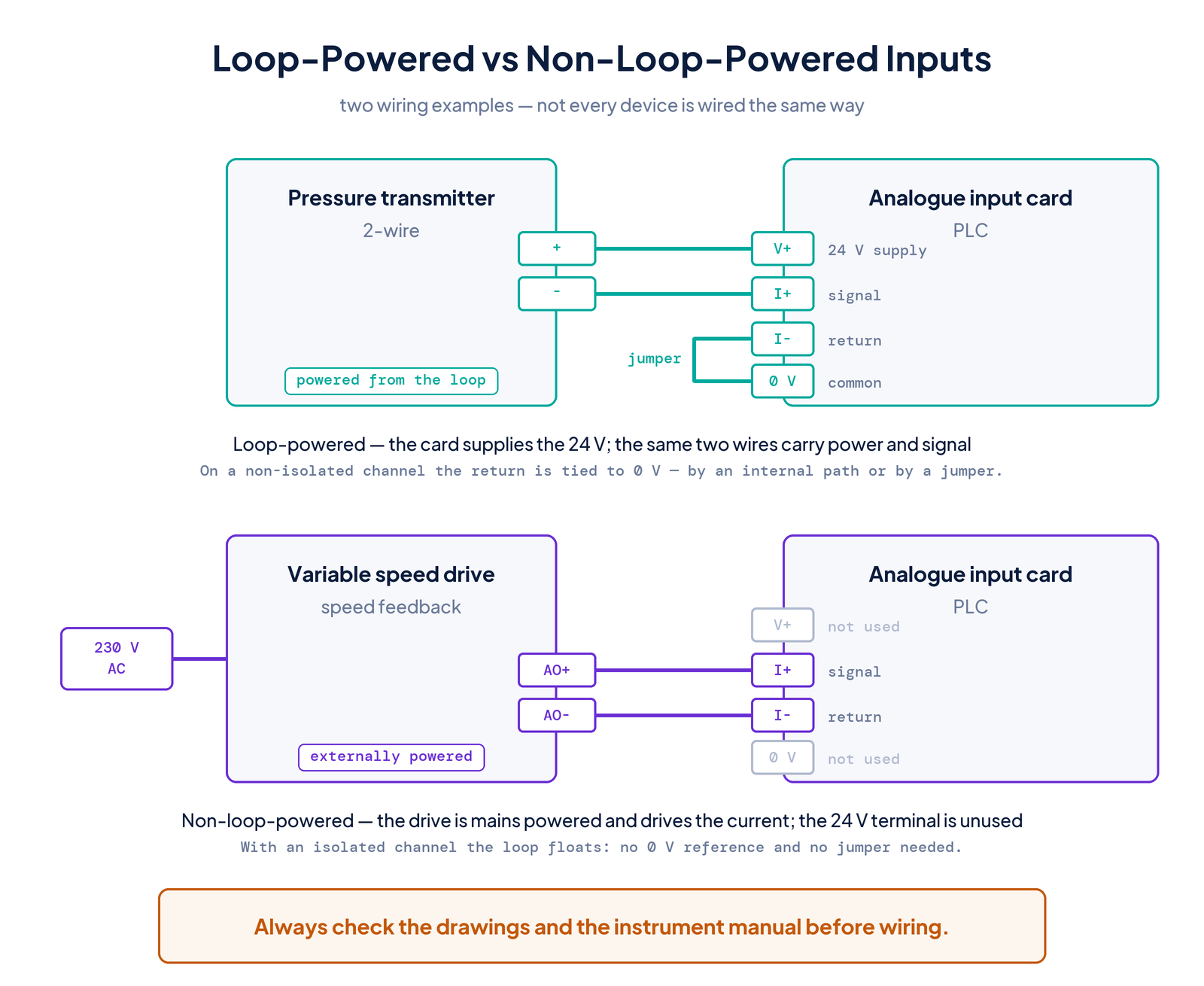
- Simulate (passive / 2-wire) — an external 24 V supply, typically from the PLC card itself, powers the loop, and the calibrator behaves like a 2-wire transmitter, sinking the regulated current. Use it against an active, loop-powered input.
A quick way to decide: look at where the loop power comes from.
- If the PLC card supplies the loop power (the usual case with a 2-wire, loop-powered transmitter), the loop already has its 24 V, so the calibrator must sink current — use Simulate.
- If the field device has its own external supply and the PLC input is passive, nothing on the loop is providing the voltage once the device is disconnected, so the calibrator must provide it — use Source.
Getting this backwards usually results in no reading or a saturated one, so it's worth confirming before you start rather than troubleshooting afterwards.
Option 2 — Simulate the signal from the transmitter. Many transmitters can simulate their own output. You drive the output to 4, 12 and 20 mA directly from the instrument, without disconnecting any wiring.
This is often the better option: you keep the installed wiring intact, you avoid the risk of reconnecting it incorrectly, and the signal travels the real path from the real device. The trade-off is that you are relying on the transmitter's own output accuracy, so it does not substitute for a later calibration.
Step 3 — Verify each point at every level
At 4, 12 and 20 mA, check two things:
- The value at the PLC. The raw signal arrives and converts to the expected value.
- The value on the HMI, in engineering units. This is the one people skip, and it's where scaling errors hide.
If the instrument measures 0–10 bar, then 12 mA must show 5 bar on the HMI. Not 50. Not 0.5. Not 5 in a different unit.
Step 4 — Confirm the range and units match the design
Here's the check that gets forgotten most often, and it's the one an auditor will notice.
Verify that the range configured in the system matches the range stated in your I/O list and design documentation.
The efficient way to handle this is to do that verification during the review of the I/O list and the loop check protocol, so that the person executing in the field only has to check against the range already stated in the protocol. Design review is the place to catch a document mismatch; the field is not.
If the instrument range is set to 0–10 bar and the design says 0–16 bar, the test is a FAIL — regardless of whether the three points read correctly for the configured range.
A loop that works but doesn't match the design is still a finding. Your test proves the installation; the documentation proves you built what you specified.
Troubleshooting
Across projects, the same three problems account for most analogue loop check failures:
- No signal, or a saturated one — usually electrical.
- Incorrect scaling — correct at 4 mA, wrong further up the range.
- Wrong channel — you inject on one loop and a different tag moves.
Here's how to work through each of them.
No signal, or a saturated one
Most likely an electrical issue. Work through it in this order:
- Confirm you are injecting correctly. Before suspecting the installation, check your own connection: that the calibrator is actually sourcing current, that its polarity is not reversed, and that the mode you selected matches how the loop is powered. A reversed calibrator lead produces exactly the same symptom as a wiring fault.
- Confirm the instrument has power. It sounds basic, but attention tends to go straight to the PLC side, and it can take hours before someone realises the device was never powered. It can be as simple as a loose terminal or a blown fuse on the 24 V DC supply.
- Measure the current at the PLC side with a multimeter. This tells you whether there is a wire break or reversed polarity. If you can't read current there, the problem is in your wiring.
- Verify the wiring against the electrical drawings, on both the PLC side and the instrument side.
- Check whether the device should be loop-powered. If a device is externally powered, it does not need loop power, and feeding 24 V into it is a common mistake that can saturate the signal. Check whether the drawing itself is wrong.
- Check the wiring instructions in the instrument manual. Sometimes the error was introduced when the drawings were drafted. If so, redline the drawings — you'll need it for the as-built revision.
Incorrect scaling
The classic: correct at 4 mA, wrong at 12 and 20 mA.
- If the range doesn't match your protocol, confirm the range in the design document first — there may be an inconsistency between the two. In that case the protocol needs a discrepancy raising against it.
- Check the instrument manual for how the range is configured, and verify that the configuration matches the range in the design document.
- Check whether the device should be loop-powered. Feeding loop power to a device that doesn't need it can produce inaccurate readings as well as saturation.
Wrong channel
You inject on one loop and a different tag moves.
- Verify in the drawings that you are monitoring the correct channel in the PLC.
- At the PLC side, check the wire labels on the adjacent channels, and on the same channel of neighbouring analogue input cards. Crossed signals usually happen where several cables land together.
What a Test Looks Like in Practice
Record results as you execute, not afterwards from memory. For each loop that means: the tag, the channel, the injected values, the values observed at the PLC and on the HMI, the outcome, and who executed it and when.
If something fails, raise it as a discrepancy, resolve it, and re-test against a known revision of the design. A failure that's documented and closed is quality evidence. A failure that's quietly corrected is a gap in your record — and it's the kind of gap that becomes expensive during qualification.
Here's what that looks like as a test in MGTrace, for an in-line load cell ranged 0–20 g: three points at 4, 12 and 20 mA, the expected value in engineering units with its tolerance, and a final check of range and unit against the I/O list. Any deviation is recorded as a punch item rather than corrected silently.
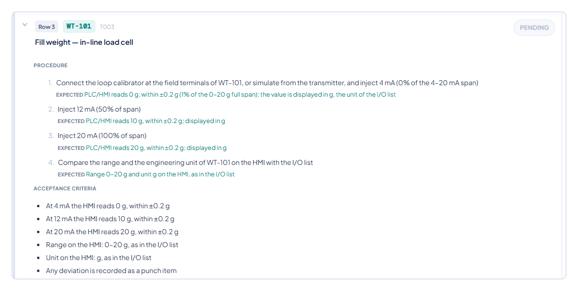
You can build the same structure as a template and apply it to every signal of that type in one click.
In Short
A loop check verifies the path, not the accuracy. Three points — 0%, 50% and 100% — are enough to prove that path is correct. Check polarity before you inject, choose the right calibrator mode for how the loop is powered, verify the value both at the PLC and in engineering units on the HMI, and confirm the configured range matches your design documentation.
Do that properly during commissioning and qualification becomes an exercise in confirming what you already know. Skip it, and you'll spend qualification chasing problems that were never qualification problems at all.