· 11 min read
Digital input and output loop checks: both states, and what happens when the wire breaks
How to test digital inputs and outputs during commissioning: what a digital loop check proves, why a DI has a third state, fail-safe wiring (NO vs NC) for alarms and level switches, the three-step test for DI and DO, NAMUR line monitoring, what to record, and a one-page test sheet.
By Eduardo Morales
Loop checkDigital I/OFail-safeCommissioningInstrumentationC&Q
A digital signal looks like the easy half of a loop check: on, off, done. It is the half where the serious mistakes hide, because a digital input has a third state nobody forces during the test, the broken wire, and what the PLC reads in that state is decided by the wiring, not by the logic. This guide covers what a digital loop check proves, how to test an input and an output in three steps instead of two, what fail-safe means at the I/O level, and what to write down.
What does a digital loop check prove?
A loop check proves the path. For a digital input (DI): the field contact changes state, the signal travels the cable, through the junction box and the marshalling terminal, into the right channel of the right card, the PLC bit follows, and the HMI shows the text the I/O list says. For a digital output (DO): the PLC bit changes, the output channel drives the relay or the solenoid, the device moves, and the feedback, if there is one, agrees.
It does not prove the logic. Whether the high-level alarm stops the pump, whether the interlock holds the valve closed, whether the sequence aborts: those are functions, specified in the FS and verified in the functional test, as the IQ, OQ, PQ guide explains. The loop check is IQ evidence: it proves the signal is wired and read as designed, so that the functional test can trust it. The 4–20 mA loop check does the same for the analogue signals.
Why a digital input has three states
Both states are the easy part: force the switch, watch the bit, watch the HMI. The third state is the cable that comes off a terminal, gets cut by a pallet truck, or corrodes in a junction box. The PLC reads something in that state too, and which something is a design decision.
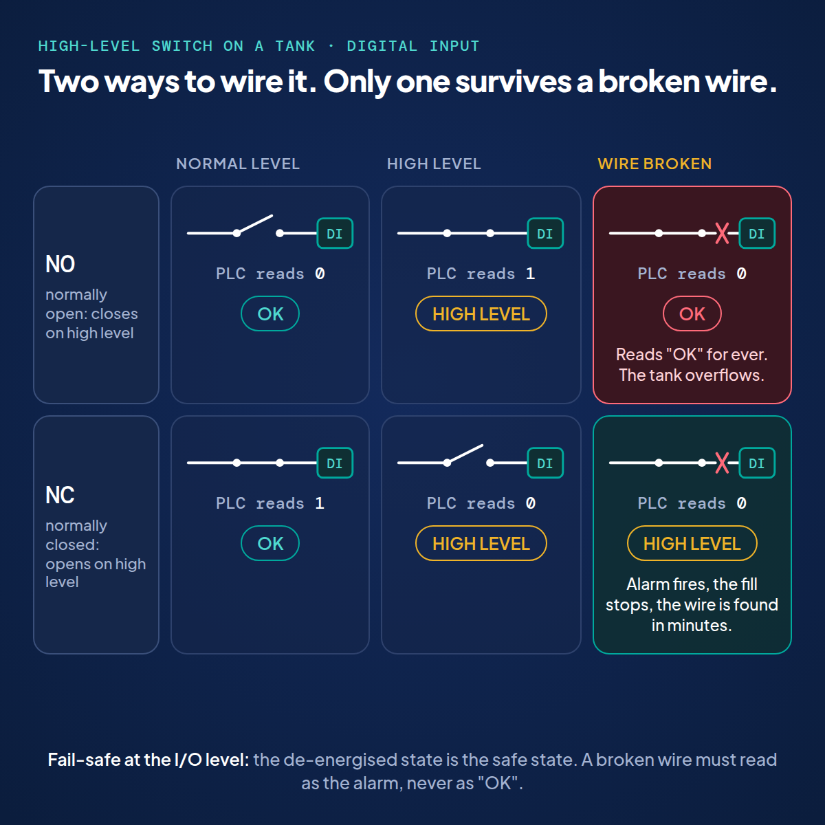
Take a high-level switch on a tank. Wired as a normally open contact that closes on high level, a broken wire reads as "no high level", for ever. The tank overflows with the PLC perfectly happy. Wired normally closed, so that it opens on high level, the same break reads as "high level": the alarm fires, the fill stops, and someone finds the cable in ten minutes.
That is what fail-safe means at the I/O level: the de-energised state is the safe state. A broken wire, a blown fuse or a dead power supply all end in the de-energised state, so that state must be the one that raises the alarm or stops the process. In practice:
- Alarm and trip contacts open on alarm. Level switches, pressure switches, door switches on guarded machinery, emergency stops: normally closed, healthy when current flows.
- Trip outputs de-energise to the safe position. A valve that must close on failure is held open by the signal and closes when it drops out; a pump that must stop runs only while the output is energised.
- Run and status signals can be normally open. "Pump running" wired NO fails to "not running", which is the conservative reading. The rule is not "everything NC"; it is "the de-energised state is the safe one, for this signal".
The decision is made in the design, written in the DS and carried in the I/O list as the contact type and the active state of every signal. The loop check is where it is verified, and where a wrong decision is caught before the functional test builds on it.
How to test a digital input
Three steps, each at the field device, not in the PLC. Forcing the bit in the controller tests nothing but the HMI; the point of the loop is the path from the field.
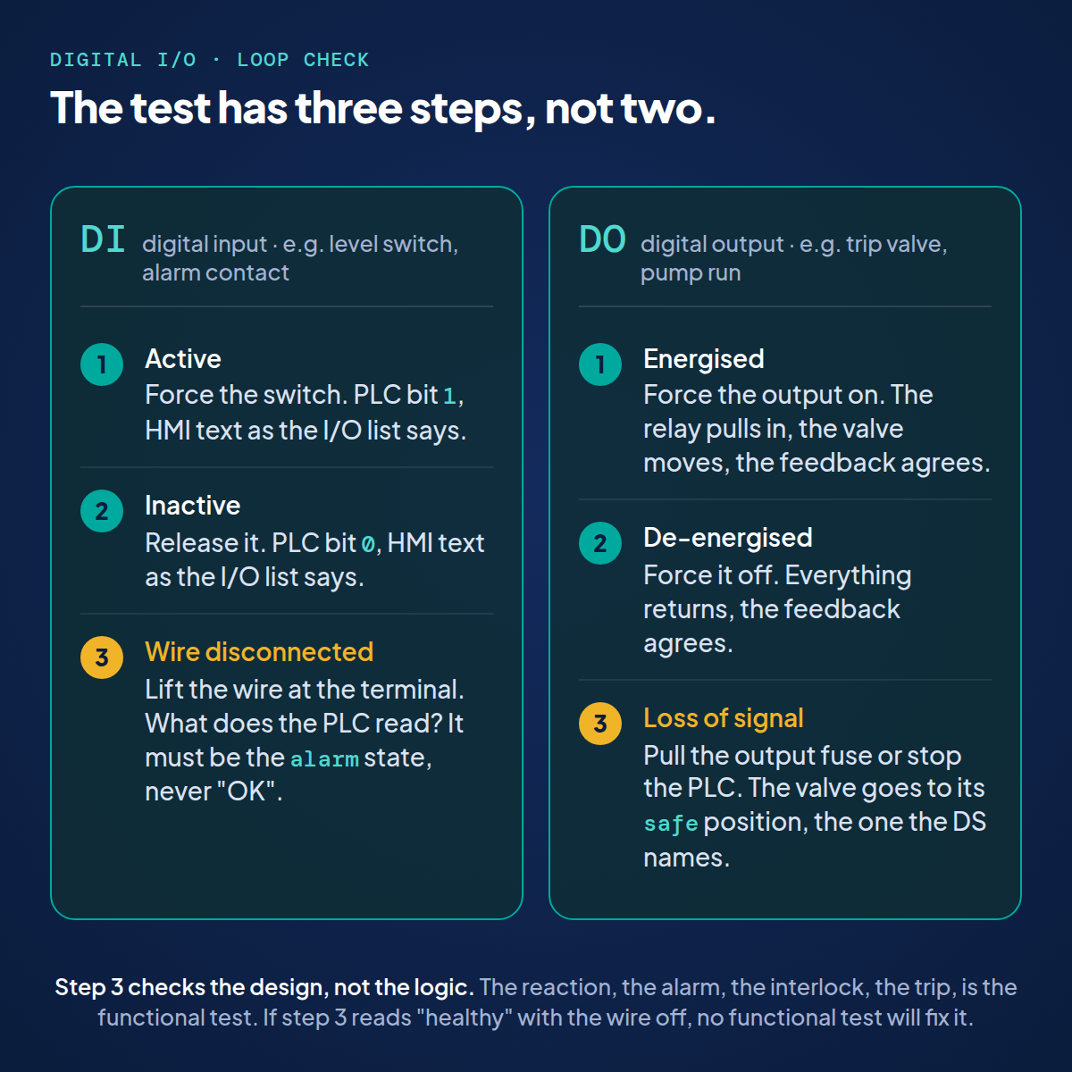
- Active. Operate the device: float the level switch, press the pressure switch's test button, open the guard. Read the PLC bit (1, or 0 for an NC contact: whatever the I/O list says is the active state) and the HMI text. Both must match the I/O list, word for word.
- Inactive. Release the device. Bit and HMI text back to the inactive state as listed.
- Wire disconnected. Lift one wire at the field terminal, or at the marshalling terminal nearest the field. Read the PLC bit and the HMI. The reading must be the alarm, trip or "not healthy" state. If it reads "OK", the signal is wired fail-dangerous, and that is a discrepancy against the design, not a failed step to re-run.
Step 3 takes thirty seconds per signal and is the one that finds the wiring errors that matter. It is also the one most protocols leave out, because "the switch works" feels like the end of the test.
How to test a digital output
The same three steps, mirrored:
- Energised. Force the output on from the PLC. The relay pulls in, the solenoid energises, the valve moves or the motor contactor closes. If there is a feedback signal, a limit switch or an auxiliary contact, it agrees, and that feedback is a DI with its own three steps.
- De-energised. Force it off. Everything returns, the feedback agrees.
- Loss of signal. Take the signal away the way a fault would: pull the output channel's fuse, or stop the PLC. The device goes to the position the DS names as its safe position: the trip valve closes, the dosing pump stops, the heater drops out. A device that stays where it was, or goes somewhere nobody wrote down, is a discrepancy against the design.
The safe position is written in the DS and the I/O list before the test, as "fails closed", "fails open", "fails as is". If it is not written anywhere, the test cannot have an expected result, and the protocol is not ready to execute.
When the third state is not enough: line monitoring
A plain contact gives the PLC two states, and the broken wire is folded into one of them. For a safety function, or for a GMP-critical alarm, that is not enough: the system has to tell a true alarm from a broken wire, so that one is acted on and the other is repaired. That is line monitoring.
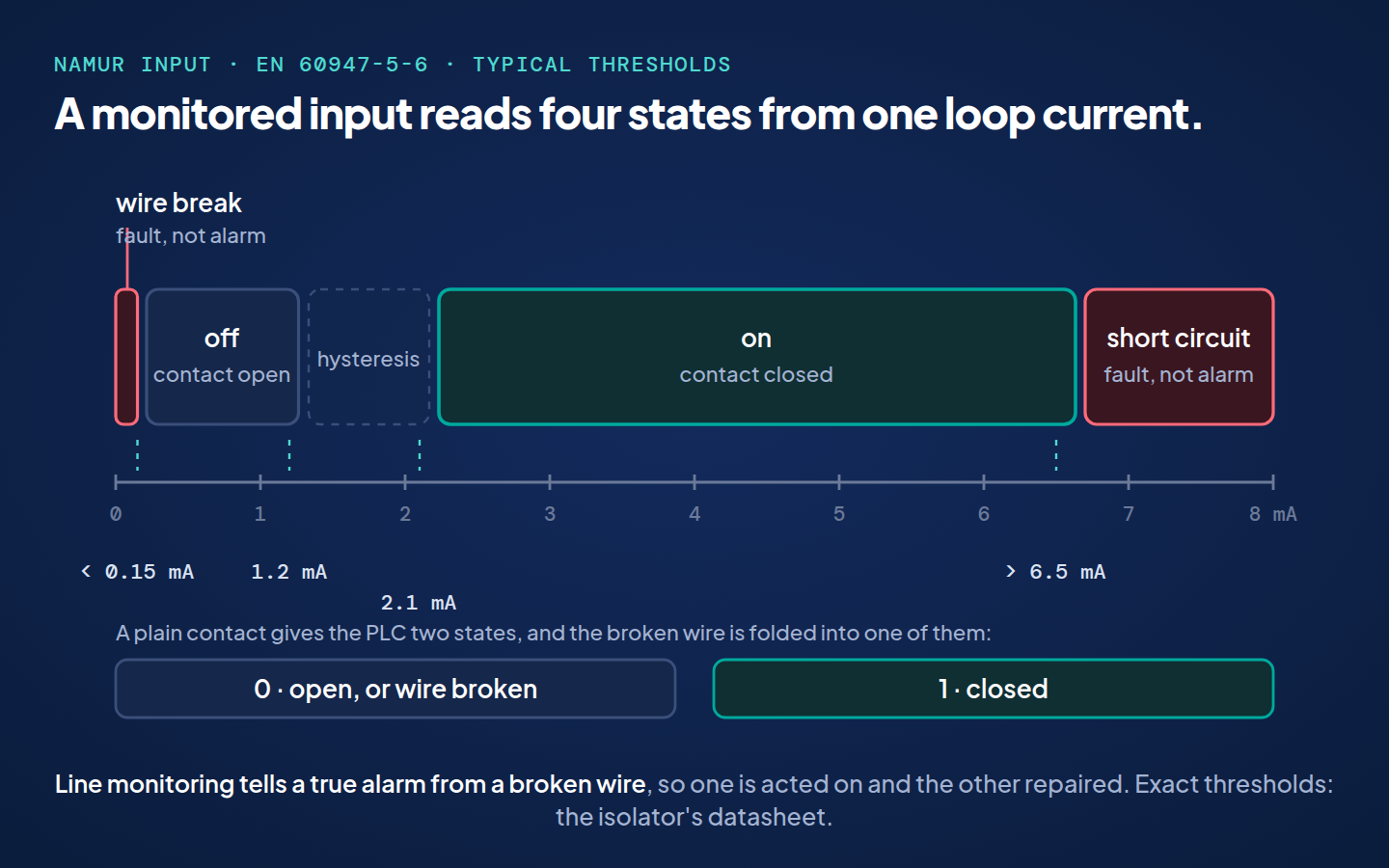
- NAMUR sensors (EN 60947-5-6) do not switch the loop on and off; they modulate a small current. The isolator reads the current: around 1 mA for "off", around 3 mA for "on", almost nothing for a broken wire, too much for a short circuit. The last two raise a fault, not an alarm.
- End-of-line resistors do the same for plain contacts in safety circuits: a resistor at the far end keeps a small current flowing in the "open" state, so that a cut wire reads differently from an open contact.
- Safety-rated I/O (SIL loops under IEC 61511) usually require it, and the loop check then has a fourth and a fifth step: wire break and short circuit, each raising the fault the DS specifies.
For most GMP process signals, a correctly wired NC contact and a step 3 in the protocol are enough. Where the DS calls for line monitoring, the loop check verifies every state the input can distinguish.
What to record
A result that cannot be re-walked by an inspector is not evidence. For every digital signal:
| What | Why |
|---|---|
| Tag, I/O address, card and channel | From the I/O list: the test is against it, not against memory. |
| Contact type and active state (NO/NC, "1 = alarm") | The design decision the third step verifies. |
| Expected and observed per step: PLC bit, HMI text | Three rows, or five with line monitoring. A tick is a claim; a value is data. |
| Fail state observed with the wire off (DI) or the signal lost (DO) | The result of step 3, as a state, not "OK". |
| Method: where the wire was lifted, how the output was dropped | So the step can be repeated the same way. |
| Discrepancy, where step 3 contradicts the design | A fail-dangerous wiring is a design change with a re-test, not a re-run. |
| Who, when, and the I/O list revision | The link to the design the test verified. |
The I/O list has to be approved before the test starts, and it has to carry the contact type and the fail state. A loop check executed against a list that is still changing produces results nobody can trace, as the traceability guide shows in detail.
Download: the digital I/O test sheet, on one page (PDF). One block for inputs, one for outputs, three steps each with the expected and observed state, the line-monitoring states where they apply, and the fields that make the sheet evidence: tag, contact type, fail state, method, I/O list revision, signatures. Download the test sheet
Six mistakes that fail a digital loop check
- Two steps instead of three. The switch works both ways, and nobody lifted the wire.
- Forcing the bit in the PLC. The HMI was tested; the cable, the terminal and the channel were not.
- An alarm contact wired normally open. The most common fail-dangerous wiring, and invisible until step 3.
- A DO with no written safe position. Step 3 has no expected result, so it passes whatever happens.
- HMI text not compared with the I/O list. "Level high" and "High level" are the same to an operator and different to an auditor walking the matrix.
- Executed before the I/O list is approved. The test proves the wiring matched a draft.
In MGTrace the loop-check tests are generated from the I/O list, one per signal, with the signal's type, address and HMI text already on the test; the executed result, the evidence and any discrepancy stay attached to the signal, which is what makes the test IQ evidence rather than a sheet in a binder. It is part of what commissioning and qualification software has to do; the three steps hold on paper too.
Frequently asked questions
Does any guideline require the disconnected-wire test?
No clause names it. EU GMP Annex 15 §3.5 asks the IQ to verify instrumentation against the design, Annex 11 §4.7 asks test scenarios to cover error handling, and IEC 61511 requires fail-safe design for safety functions. The disconnected-wire step is how the first two are shown for a digital signal: it verifies that the installed wiring produces the fail state the design specifies. An inspector will not ask for the step by name; they will ask what happens when the cable breaks, and the step is the answer.
Should an alarm contact be normally open or normally closed?
Normally closed, so that it opens on alarm and a broken wire reads as the alarm. The same for trips, emergency stops and guard switches. Status signals that carry no safety or quality consequence, "pump running" or "door closed", can be normally open, as long as the de-energised reading is the conservative one.
Should the loop check verify the interlock?
No. The loop check verifies that the signal reaches the PLC as designed, in every state. Whether the PLC does the right thing with it is the functional test, written from the FS. Mixing the two produces a loop check that cannot fail on wiring because it passed on logic, and the other way round.
Can I force the signal in the PLC instead of at the field device?
Not for a loop check. Forcing the bit tests the HMI and the program, not the path from the field. The device is operated at the field, or the wire is lifted at the field terminal; the marshalling terminal is the closest acceptable point when the device cannot be operated safely.
What about a digital output with a feedback switch?
Test both. The DO has its three steps, energised, de-energised and loss of signal; the feedback is a digital input with its own three steps, and the loop check records that the feedback agrees with the output in each state. A valve whose limit switch says "closed" while the valve is open fails the functional test later for a reason that should have been caught here.
In short. A digital loop check proves the path in every state the signal can take. For an input that means active, inactive and the wire disconnected, and the third must read as the alarm. For an output it means energised, de-energised and the signal lost, and the third must land on the safe position the DS names. Where the design calls for line monitoring, verify every state it distinguishes. Write the expected state before the test, record the observed one, and treat a fail-dangerous reading as a design discrepancy, not a re-run.